
On the 8 hour drive back from Moogfest 2012, I had a lot of ideas and one of them was to modify my controller that I built as part of the Moog 3rd Annual Circuit Bending Challenge to control the Les Paul Google Doodle. This is a YouTube video showing the first version of the guitar. Most of the components were purchased at Radio Shack. Many thanks to the Arduino Community to make it so easy to build micro-controller based devices.
To program the ATMega chip that comes as part of the Mintduino box, I use an Arduino UNO since it uses the same chip. At this time I do not see the UNO for sale on the radioshack web site. The Arduino Micro Arduino Atmega32u4 Microcontroller can be used to program the Mintduino if you load it with a simple program to copy data from USB serial port to the hardware serial port it has. |
    |

The first part of the build was to print out a picture of a guitar on legal size paper. This allowed me to make the guitar 14 inches long. The picture was then glued to a piece of 1/4 inch plywood and cut out.


The next step was to drill holes that are used to mount the switches and to glue in the switches with a hot glue gun. To make the guitar look alot better and be more durable, I printed a second copy of the picture and then laminated it. The laminated picture was then attached to the body using the mounting nuts on the switches. For the mark II upgrade I added a joystick and a center off toggle switch.


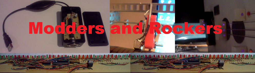
The mark I guitar used two 8-1 analog multiplexor chips (CD4051) to scan the switches. The mark I was an add-on to an existing controller. The mark II guitar is a standalone midi controller so it has it's own power regulator and battery. The mark II circuit board contains the microcontroller, the diode matrix and the power components. There are alot of wires that go to the switches and joystick. At one end is a power switch and at the other is a 5-pin DIN conector for the midi out. I re-used an old disk drive ribbon cable for most of the connections to the switches.


Some of the initial testing was done using a prototyping system. This allowed the basic microcontroller to be tested.


As the hardware build progressed, I switched to using in-circuit programming. Initially I would program the microcontroller in the UNO and then move it to the guitar. Once I had confidence that the hardware was correct I used the UNO board as a USB to serial adaptor. The four wires are GND, RST, RX and TX.
The software of the guitar is basically split into three components. Scanning the switches. Scanning the analog controls. Processing the mode switch. The center off mode switch when in the center position makes the joystick send pitch bend for one axis and channel control messages on the other axis. In the up position, the pitch bend axis is replaced with a second channel control message.


One of the devices I test with is using the Animoog software on an IPad Touch with an IRig Midi interface. This does not seem to use the pitch bend messages which is why I added the mode 1 feature.
When the mode switch is in control position, the software can be programmed to do many things. This is where you can get creative. Things such as :-


