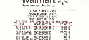
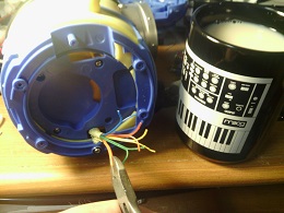
I wanted something that would be loud, so I also looked at an alarm clock and a CD radio boombox. The boombox has the best volume but I was not sure what sort of circuit
bend I could do with it. The alarm clock has so nice pieces including some nice tactile switches. Both Stuart and the alarm clock had the same type of loud speaker. The
tape recorder had a better loud speaker.
|
|
|
Materials
Bill of materials goes here
Misc stuff
Hookup wire can be from many sources. For this project I mostly used an old disk drive ribbon cable. I also
used wire from an old computer mouse. Wood glue and hot glue are used to assemble the project. A small amount of black and gold spray
paint was used.
|
|
|
|
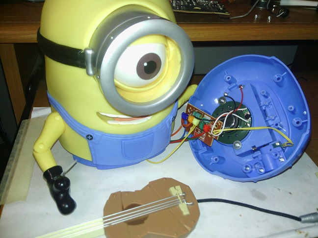
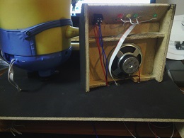
Stuart's body is held together by tri-wing screws. If you turn Stuart over, you can see cross point screws that open the battery compartment and the tri-wing screws that hold his body together. Using a tri-wing screwdriver remove the tri-wing screws and seperate his legs from his body.
|
|
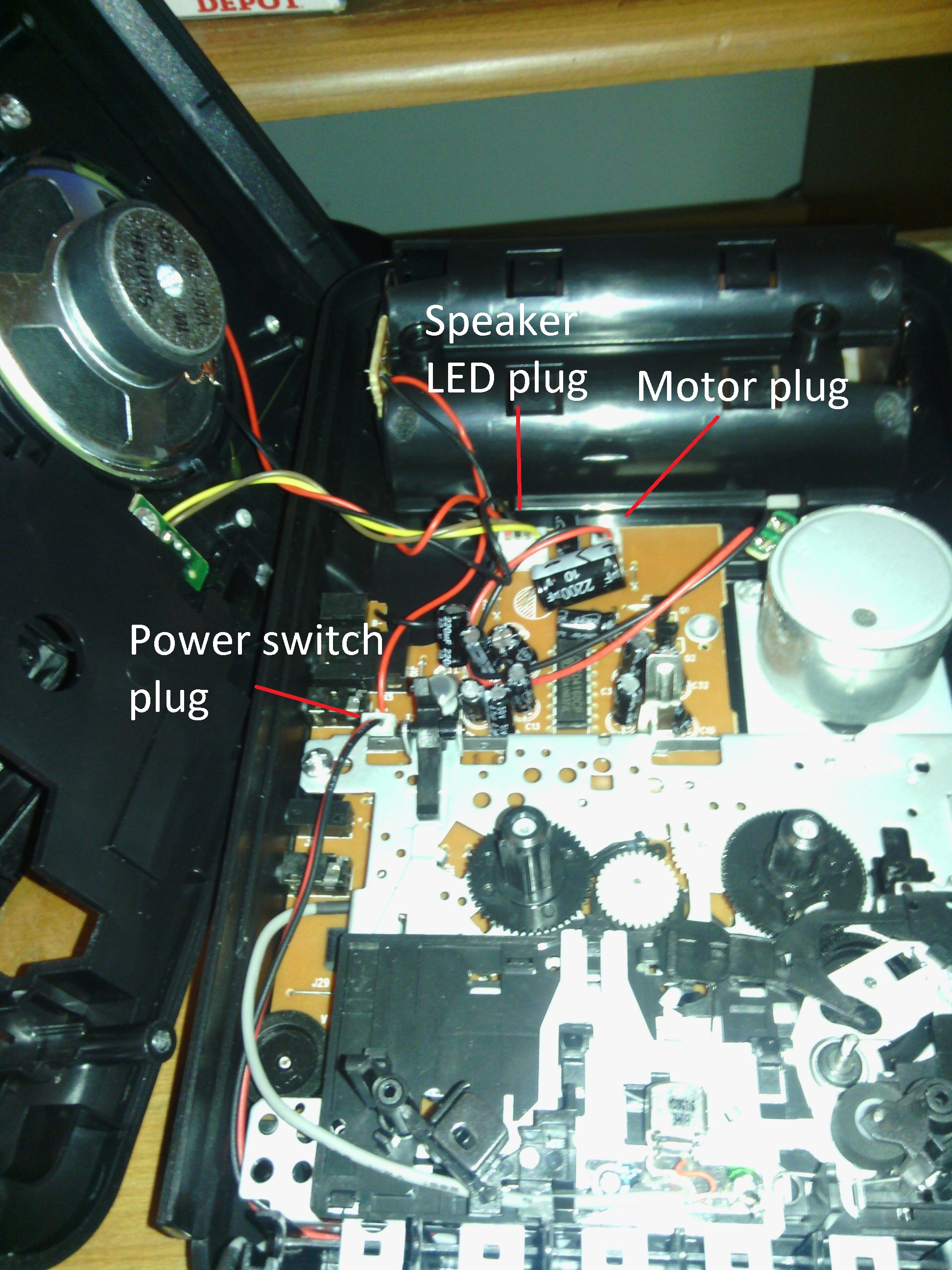
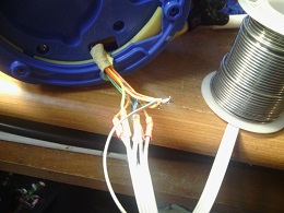
The circuit board that has the sound chip is connected to the switches in the upper part of his body by color coded plugs and sockets. A pair of yellow wires go to the switch on his hip that is activated by the guitar plug. A pair of white wires go to the speaker. A red and black wire go to the battery holder. Click on image to see what to do.
|  |
|
Unsolder or cut the yellow wires from the hip switch. Cut the red and black wires where they connect to the battery compartment. Unsolder or cut the white wires where they connect to the speaker. You can now remove the screws that hold down the circuit board and remove it.
|
 |
Cut off each of the plugs leaving just 1/2 of an inch or so connected to the plug. This allows the plugs to be used again if you want to. | |
| Connect one wire of each of the pairs together (5 wires). Using 6 pieces of hookup wire, connect one to the 5 that are joined to gether and one each to the other wire of each pair. On the back of Stuart is a piece of plastic that looks like it could have been used to mount a slide switch. Remove the piece of plastic and run the six wires out through it. You can unscrew the piece of plastic that hold the hip switch together.
| 
|
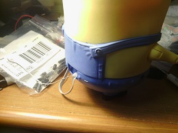 |
With the wires routed out the back of Stuart, you can now screw the top and bottom parts back together using the tri-wing screws.
|
|
|
|
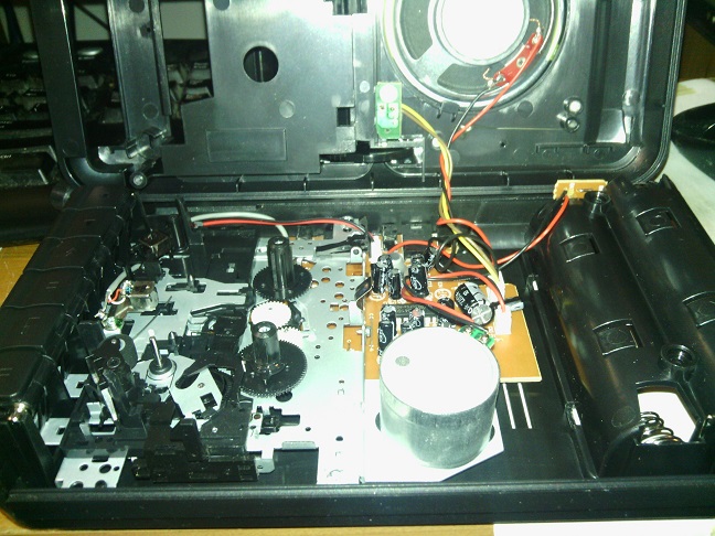
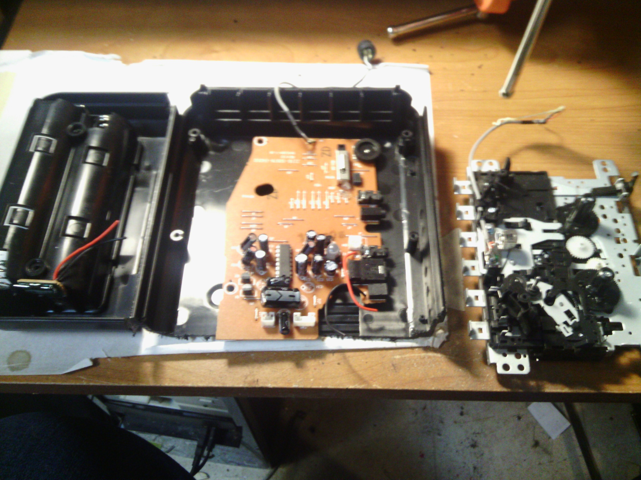
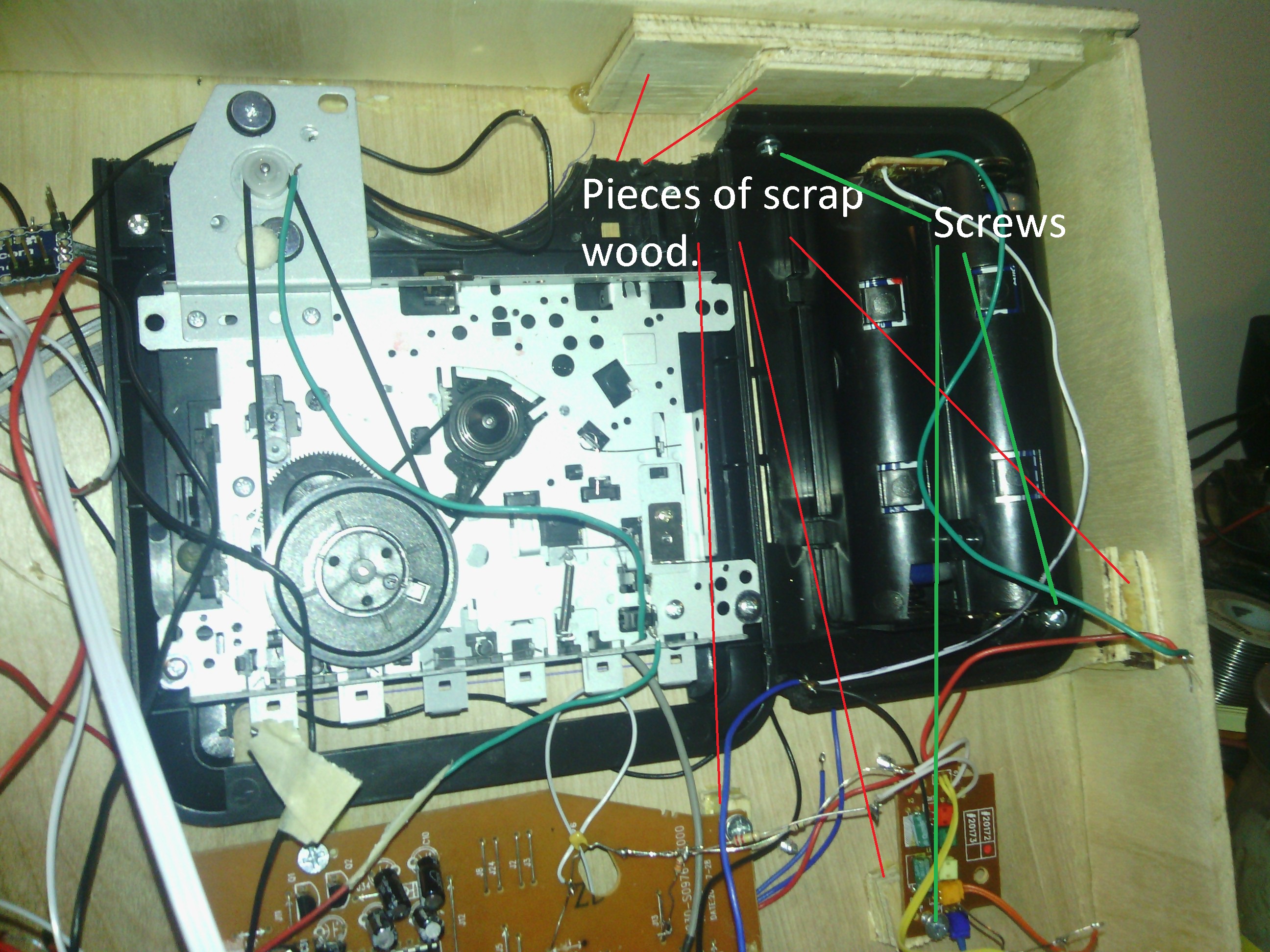
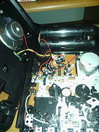
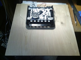
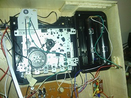
On the underside of the tape recorder you can see two crosspoint screws. Removing the battery compartment cover reveals two more. Remove the four screws and the top and bottom of the tape recorder can be seperated. The tape mechanism is held in place by a few more screws. The motor is connected to the circuit board by a plug and socket. The speaker and the led is connected using another plug and socket. The third plug and socket is connected to the switch that is activated when the play, fast forward or rewind functions are engaged. This switch turns on the power. Click on image to see more detail.
|  |
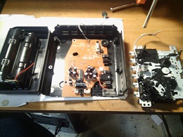 |
Cut the red and black wires to the battery holder. Unscrew the circuit board from the base. You can now remove the mechanism and circuit board from the case. Unscrew the plastic speaker grill. This will be used as part of the guitar amp. Cut the base so that the battery compartment is separated.
|
|
Cut the top part of the case across where the speaker grill had been just past the hinges for the cassette tape holder. The piece will be glued into the plinth base to mount the cassette mechanism and raise the guitar case.
|  |
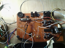 |
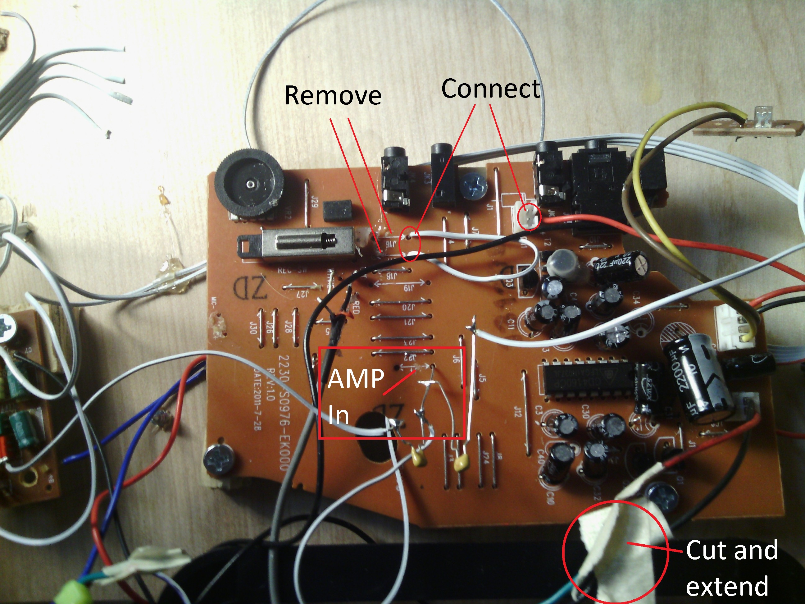
The changes to the tape circuit board are minimal. Remove the wire links J16 and J17. These are the Main amplifier output of the tape chip and the loud speaker connectiosn to the
record/playback switch. Use a piece of wire and join the J16 and J17 holes that are nearest to the IC. This will permanently connect the speaker to the amplifier output.
The next changes makes the tape recorder circuit always on. With a piece of wire or a solder blob, join the two pins of the power socket. The lead to the power switch should be unplugged and
the lead should be unsoldered from the switch.
The wire jumper J4 is the connection from the volume control wiper to the main amplifier in the tape IC. This is where we will connect the sound signals from
Stuart's circuit board and the output from the oscillator (NE556).
The red and black leads to the tape motor need to be lengthened. Cut both leads. Using hookup wire, connect one red lead to one side of the power switch on the tape mechanism
and connect the other red lead to the other side of the switch. Connect the two black leads together with more hookup wire. Now the motor should only turn on
when the play/record/rewind controls are activated.
|
|
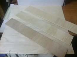 |
To make the base, cut the 2ft by 2ft 1/4 inch ply in half. Take one of the half and cut it into half. This gives you the 12inch by 12inch piece that forms the top of the base. From the other 12 inch by 12inch piece cut three 2 inch wide strips. Glue the three 2inch pieces to make the sides of the base.
|
|
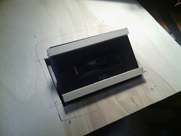
Trace the cassette tape lid onto a piece of paper and use it to mark where you want to cut out a hole so the lid can open. You can use a sharp craft knife to cut out the piece. Make several passes with the knife and it is easy to cut through the 1/4 inch ply. Once the hole has been cut, you need to make sure that the lid will open when you press the stop/eject button on the cassette mechanism. Note that the tape deck is mounted "Upside Down". That is when you open the lid, the tape opening faces the back of the base. This allows the guitar case to tilt towards the front of the base.
|  |
|
|
Take the plastic speaker grill and cut a piece of 1/4 inch ply to the same size. Cut two strips that are about 1.5 inches wide and 5 inches long for the sides of the amp case. Use the grill as a guide and cut slopes in the sides so that the amp control panel will be at an angle. The control panel is also made out of a 1.5 inch wide strip that is the length of the width of the grill.
|
|
Mark the position of the speaker on the piece of plywood and using a craft knife or by drilling holes, cut out the speaker opening. This is going to be behind the plastic grill so it does not have to be perfect in shape. With a pencil mark a line horizontally across the control panel half way up. Use a 1/4 inch drill bit to make a hole to mount the power switch. Drill four more holes to fit the LEDs you are using.
Before assembling the pieces, you want to paint them. The sides and the main speaker mount I painted black. The control panel I painted gold.
|
 |
To assemble the guitar amp case, hot glue the plastic grill to the ply wood aligning the speaker holes. Then glue on the sides so that the front edge of the side pieces is flush with the front of the grill. I use both wood glue for strength and hot glue to hold the sides in place. Glue on the control panel. Using both hot glue and wood glue makes the assembly fairly straight forward.
Finally hot glue the speaker over the speaker hole.
|
|
|
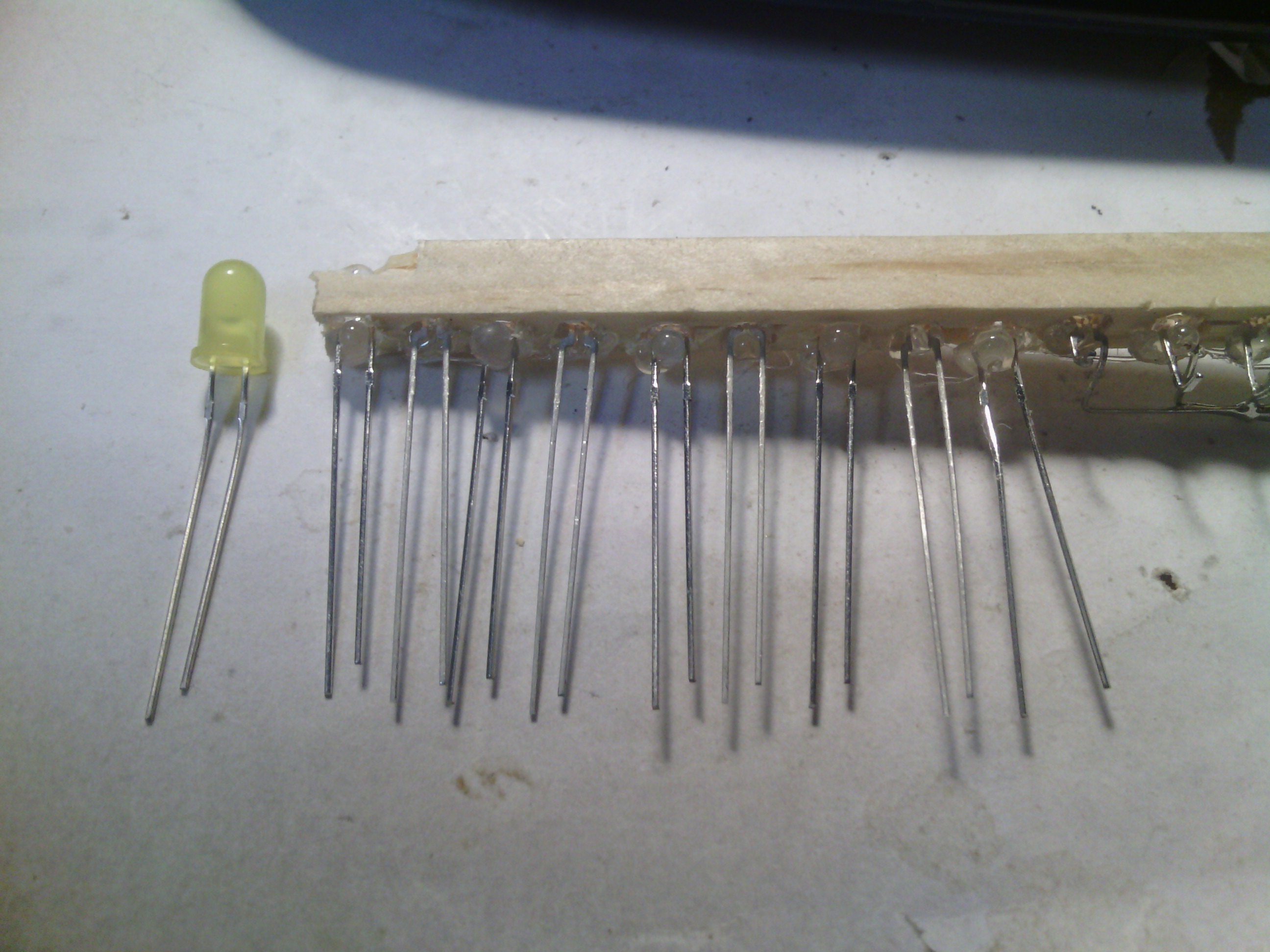
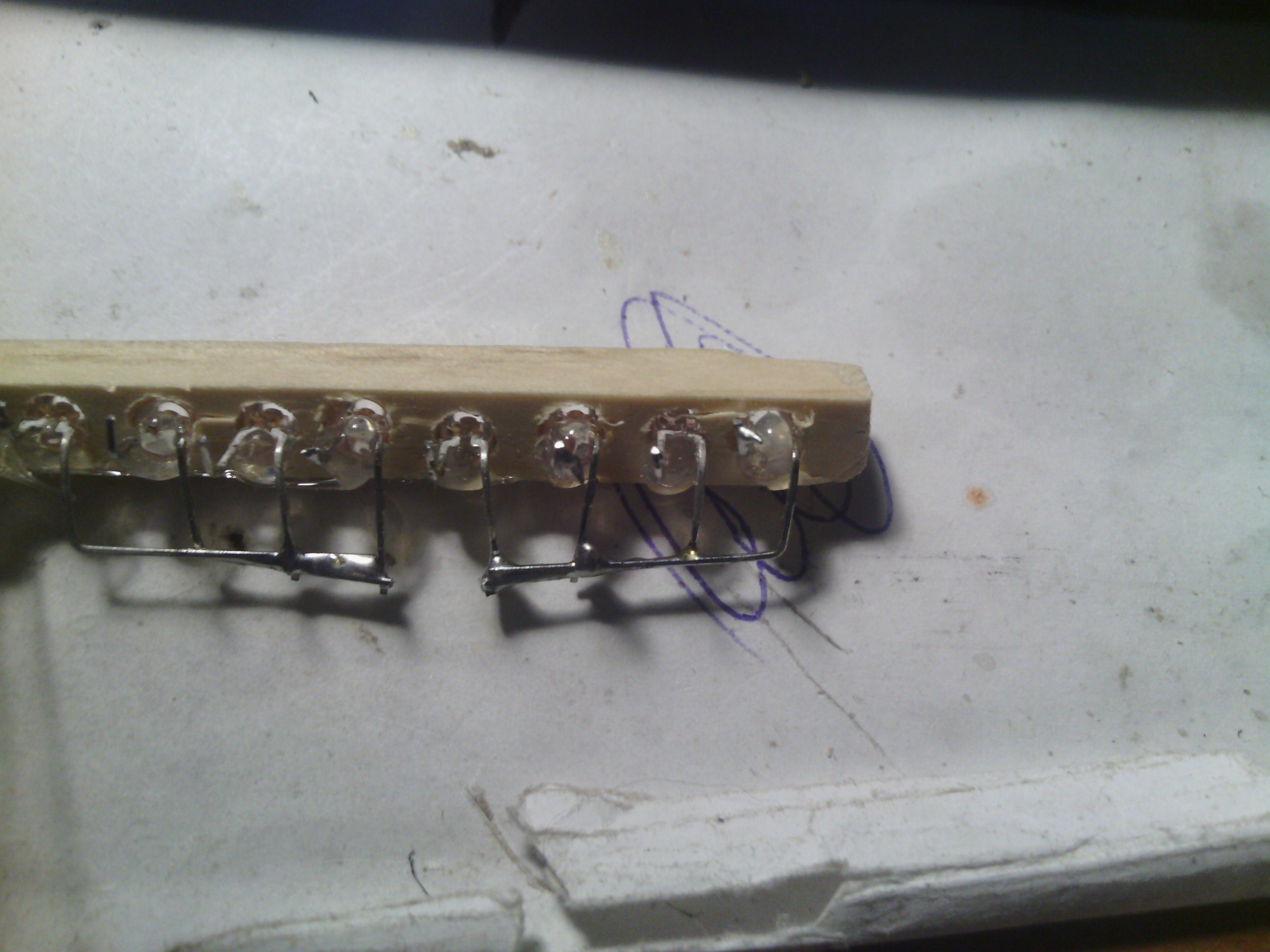
The guitar case has the 12 Infra Red beams that are used to replace the mechanical switches. Cut two 1/2 inch wide strips that are 6 inches long from the pieces of scrap plywood. Mark the position of the 12 holes in each piece. The holes are 1/2 inch apart starting 1/4 inch from the end. For the IR photo diodes and IR LEDs I used a 9/64ths drill bit was the correct size. The holes should be drilled 1/4 of an inch from one of the long edges. Cut three more pieces that are 7.5 by 3 inches. Trace around the guitar and cut out the guitar shape in two of the pieces. To assemble the case, glue the two guitar cutouts onto the third piece as a base. Then glue the two IR beam pieces so that the holes line up across the case.
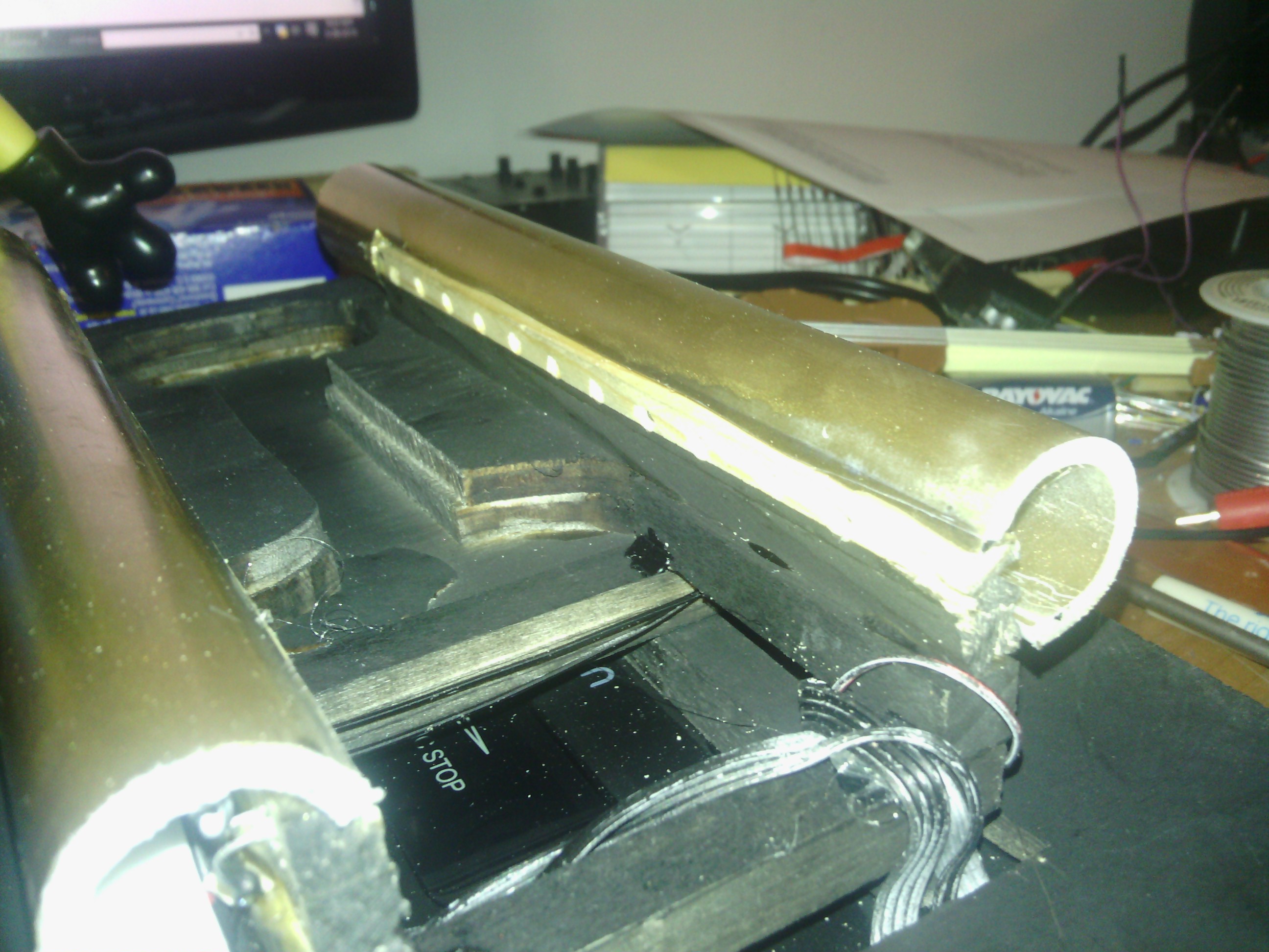
Paint the case. I used black paint to paint the guitar case. Later two pieces of plastic pipe are used to cover the wiring of the LEDs and photo diodes. I painted them gold.
|  |
|
|
|
 |
The battery compartment, the tape circuit board and the sound board from Stuart are mounted using 1/2 inch number 6 wood screws.
To give the screws something to screw into, I used bits of scrap wood glued to where I wanted to use a screw. The scrap spaces
the board off the plywood and stops the wood screw from poking through the 1/4 inch ply.
|
|
|
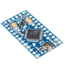
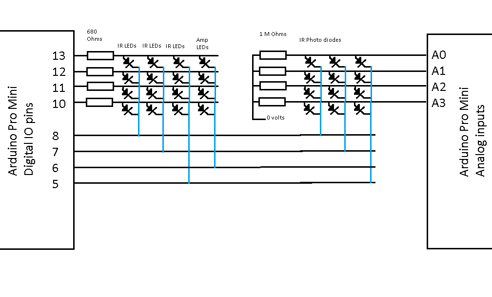
The software running on the Arduino Pro Mini scans the IR beams and controls two
switches on the Stuart circuit board. There are 12 IR photo diodes, 12 IR LEDs and 4
other LEDs. These are handled by 8 digital IO pins and 4 analog inputs using a technique called multiplexing.
- Pins 13,12,11,10
- These pins are normally configured as inputs so that they
provide no current. They are connected via 680 ohm resistors to the anode groups of the LEDs.
- Pins 8,7,6,5
- These pins are normally configured as inputs so that they
provide no current. They are connected to the cathode groups of the LEDs and photo diodes.
- Pins A0,A1,A2,A3
- These pins have 1 M ohm pull downs to 0 volts. They are wired
to the anode groups of the photo diodes.
To test an IR beam, one of the cathode group pins is configured as an OUTPUT and is set to LOW. One of the
LED anode group pins is configured as an OUTPUT and set HIGH. This turns on one of the LEDs. The corresponding
IR photo diode is read by doing an analog read on the correct analog input pin. The value read is stored in
an array which has one entry for each IR photo diode. Next the LED anode group output is configured back as an
INPUT. This turns the LED off. The IR photo diode is read again and the value stored into a second array. The difference
between these two values is used to determine if the IR beam is being broken.
The next anode group pin is configured as an OUTPUT and set HIGH. The corresponding analog input is read and stored. The
pin is configured back as an INPUT and the analog input is read again and stored in the 2nd array. This is repeated for the 3rd and 4th anode
group pins.
The next cathode group is selected by configuring the previous pin to INPUT. Configuring the new pin as an OUTPUT and setting it LOW.
Then each of the IR beams is read as before using the anode group pins. Once all 12 IR beams has
been checked, the software can use the 1st and 2nd arrays to determine which if any of the IR beams
has been broken.
|
|
| |
|
- stuart.ino
- This is the main source for the Stuart Arduino Sketch
- tunes.h
- This has a few helper definitions for Midi.
|
 |
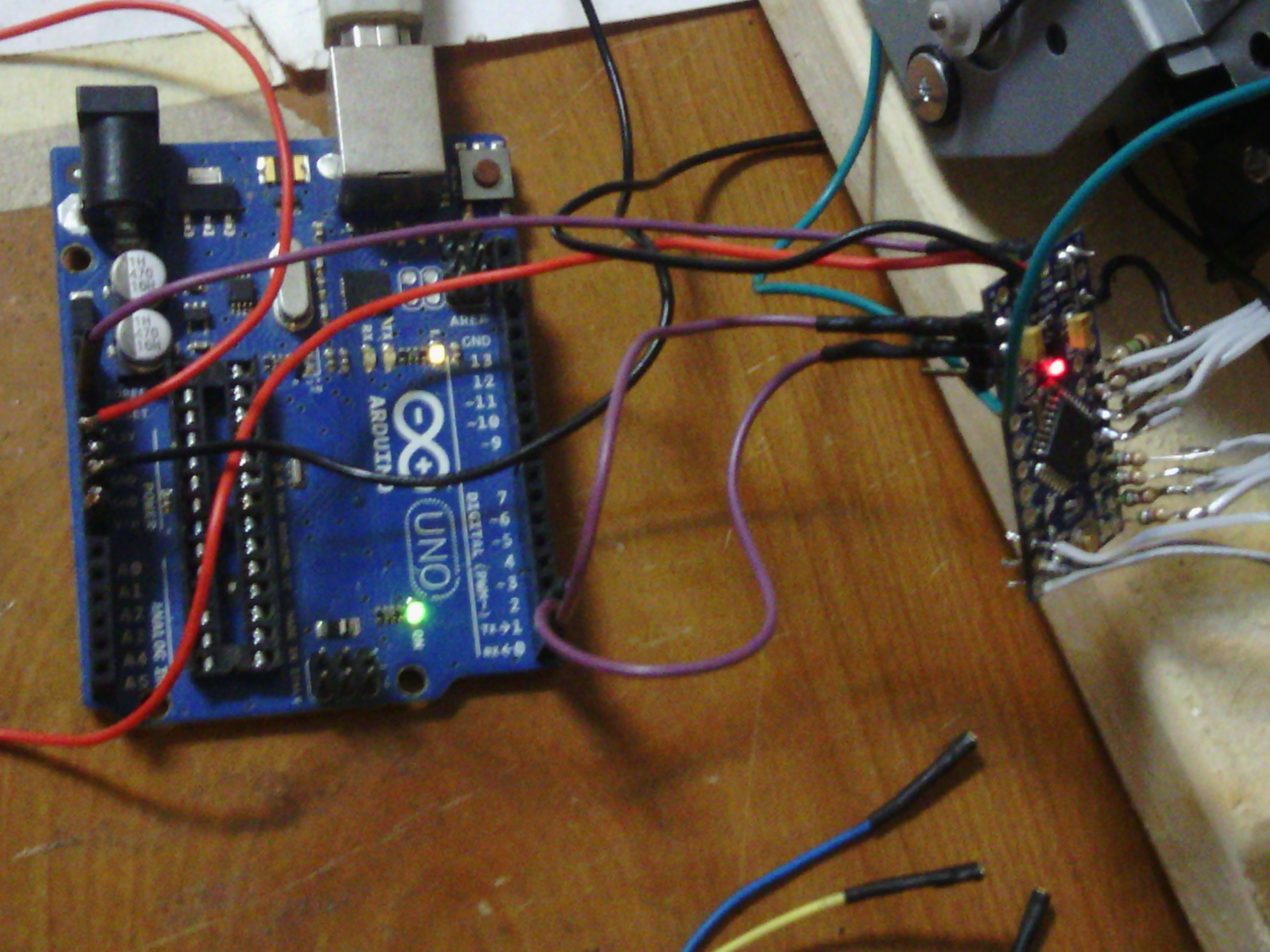
To upload the sketch into the Arduino Pro Mini, you need a USB to serial interface. I use an Arduino UNO with the 328 cpu chip removed.
To upload you connect the UNO TX to the TX on the Pro, the RX on the UNO to the RX on the Pro, the Reset on the UNO to the RST on the Pro and
the Gnd on the UNO to the Gnd on the Pro.
In the Arduino IDE, select the board as "Arduino Pro or Pro Mini". Select the correct COM port. You should now be able to upload the sketch.
| |