|
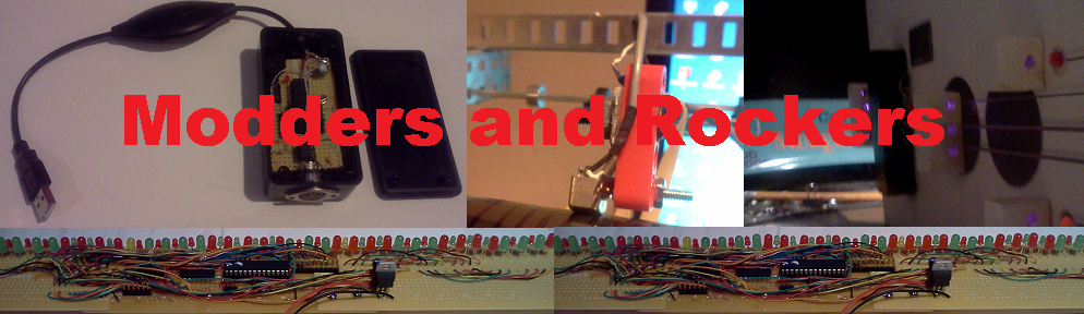
My Werkstatt Workshop projects. Mother of Werkstatt Mods. | Midi Keyboard Interface (7/17) | Updated: 7/29/17 Keyboard | Key mod points | Arduino |
Octave shift and Arpeggiator |
Werkstatt Besen Gittare (Broomstick Guitar) |
Mutter zweiunddreisig |
Midi Keyboard Interface (7/17) |
What is the WERKSTATT?The Werkstatt was designed by Moog Engineers for Moogfest 2014. The Moogfest Engineer Package included two 3 hour workshops were you built a Werkstatt and then was shown how it works and how it could be modified. Description of the Werstatt workshops from the official Moog siteWelcome to the Moog Music Synth building workshop at Moogfest 2014. The project for this event is called "Werkstatt" (German for Workshop or Garage). Werkstatt is an analog patchable synth featuring 1 VCO, 1 Moog Ladder VCF, a VCA, an Envelope Generator, a LFO, and a 1-octave keyboard with glide. It is a patchable synth with CV Ins and Outs available on a column of breadboard connections. It is also designed with hackability in mind for the intrepid analog explorer. The workshop is devoted to building and understanding the Werkstatt and hopefully inspiring a desire to explore the world of Moog synths and analog musical electronics.
The Werkstatt keyboard controller is made up of a number of building blocks.
A simple free running oscillator using one of the schmitt triggers in U14 drives a couple of dividers to make a 4 bit counter. Two bits are decoded using a 4051 8 to 1 analog switch for the columns and another decodes the other two bits to select the row. Note that only 13 of the 16 possible switches are used. When a switch is pressed, it connects a row and a column. Diodes are used for isolation so that pressing two switches does not short out two of the columns. The row multiplexor output is fed to the key press trigger logic. The trigger logic clocks 4 data latches that save the value of the counter. The output from the latches is converted to an analog value using an R-2R ladder. The analog value is scaled and buffered. The key press logic also generates a number of signals.
The counter reset is used to handle the situations where more than one key is pressed. If you hold down two keys on the Werkstatt, you will notice that only the lower one sounds. This is because the counter is reset back to 0 when a key press is detected. Although there are no test points in the keyboard controller area of the circuit board, you can attach wires to circuit traces that allow you to make a number of mods. Where possible the wires are attached by using a via (hole) where a trace goes from one side of the board to another. This is a list of the keyboard controller wires I have added so far.
Keyboard ConnectionsTo drive the keyboard logic from an Arduino, I added wires from the output of the row multiplexor (input to thr keyboard trigger logic). One to each of the counter outputs so the Arduino can read the counter value. Later I added a wire to the kb clock so that the Arduino generates the clock. Originally the clock was free running. 
The pin numbers on the Arduino can be changed if the software is changed to match. I have a lookup table to remap the counter signal values. Midi In and OutThe Midi input and output circuits are straight forward. The Midi output just needs some current limiting resistors. The Midi input uses an optical isolator. I have used the 6N138 photo darlington device. 
These are the initial sources. Create a werkstatt folder and copy these files into it. The in the Arduino program open werkstatt.ino |
|
